When designing high-voltage networks, a protection plan must be drawn up to ensure the safety of people but also to preserve the continuity of operation in the event of a fault in the electrical installation.
For this purpose, it is necessary to determine for each point of the installation, the maximum and minimum prospective short-circuit currents for each type of fault: three-phase, two-phase, two-phase with earthing and single-phase. The international standard IEC 60909-0, “Short-circuit currents in three-phase a.c. systems” uses the symmetrical components method. It is based on the introduction of an equivalent voltage source at the short-circuit point, with all network power supplies, synchronous and asynchronous machines being replaced by their internal impedances. In order to calculate the values of the balanced and unbalanced short-circuit currents, the currents in each phase are obtained by adding the currents relative to the three symmetrical components of the network (positive-sequence, negative sequence and zero-sequence). This requires knowledge of the impedances of all the installation components in each of the three systems.
Unlike low voltage where overcurrent detection and cut-off are generally managed on the same device, in high voltage the functions are split. The overcurrent detection is performed via current transformers connected to a protection relay which will give the tripping order to the breaking device. The knowledge of the short-circuit currents will make it possible to define the tripping thresholds to be set on the protection relay(s).
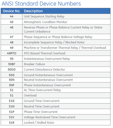
The functions of the protection relays are standardized and described in the ANSI / IEEE C37.2 standard:

Figure 1: IEEE C37.2 excerpt
Modeling and sizing with elec calc™
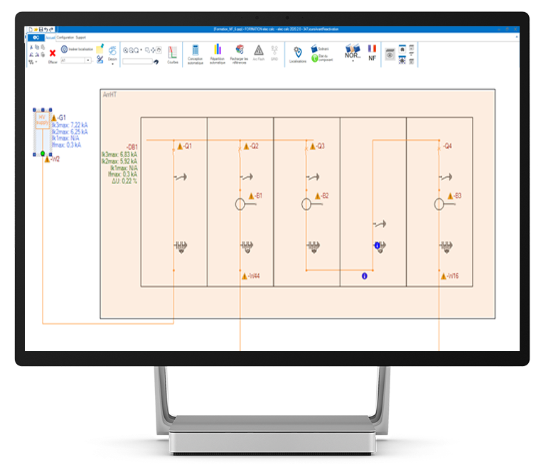
calc™ allows to model high and low voltage in the same project; all calculations including short-circuit currents according to IEC 60909-0 are performed in real time as well as the verification of all normative constraints. The drawing of the single-wire diagram is completely free and can be accelerated by using the standard cells available in the library.

Figure 2: example of an incoming substation modeled under elec calc™
elec calc™ can be used to enter and check the settings of independent-time overcurrent relays, i.e., the following ANSI codes:
– 50 : Instantaneous phase overcurrent
– 51: Time-delayed phase overcurrent
– 50N : Instantaneous earth overcurrent
– 51N: Time-delayed earth overcurrent

Figure 3: HV-LV selectivity study on elec calc™
The entering of these thresholds will also make it possible to carry out the selectivity study on all the voltage levels of the project; it will be possible to carry out the time-delay and current adjustments in real time with the curve tool. It is possible to integrate the equipment references on all the components of the project in order to retrieve the technical data from our multi-manufacturer database.
